![]()

|
|

Rapid Sand Filtrationby Dottie Schmitt and Christie ShinaultRapid sand filtration is the flow of water through a bed of granular media, normally following settling basins in conventional water treatment trains. The purpose of this filtration is to remove any particulate matter left over after flocculation and settling. The filter process operates based on two principles, mechanical straining and physical adsorption. Sand filtration is a "physical-chemical process for separating suspended and colloidal impurities from water by passage through a bed of granular material. Water fills the pores of the filter medium, and the impurities are adsorbed on the surface of the grains or trapped in the openings." (Culp, page 91). The key to this process is the relative grain size of the filter medium. 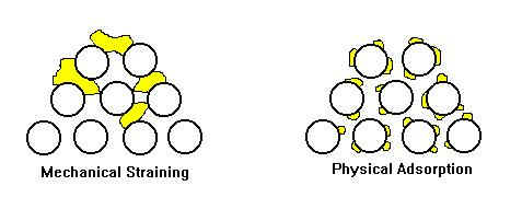
Schematic of basic filtration principles by D. Schmitt Rapid sand filtration is contrasted to slow sand filtration by increased flow rate, method of cleaning the filter bed. A rapid sand filter can operate up to 40 times faster than a slow sand filter. Rapid sand filters are cleaned often, usually daily, by reversing the flow of water through the entire filter bed, referred to as backwashing. Slow sand filters are cleaned less frequently by removal of the top layer of media.  The Filtration Process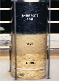 Photo of cross
section of typical sand filter, courtesy of Blacksburg Water Treatment Plant.
Taken by Christie Shinault Photo of cross
section of typical sand filter, courtesy of Blacksburg Water Treatment Plant.
Taken by Christie Shinault In its most basic form, the filter is composed of three components, the inlet, the filter bed and the outlet. The wastewater influent is distributed over the media bed, then gravity pulls it through the filter at a rate of 1 - 2 g.p.m./sq.ft. It is then collected by the outlet component and distributed to storage tanks for chlorination, or pump stations.
Sand filtration is of particular importance in that it effectively removes pathogenic microorganisms. Giardia lamblia is a major concern in drinking water supplies, as it forms cysts that cannot be killed by traditional chlorination. Filter BedThe most effective is a coarse to fine pore size (the hydraulic radius of the stream line between particles). This allows for a more complete use of the bed area and reduced backwash frequency. Mixed media filter beds are the most common. An ideal mixed media bed may be composed of approximately 30-60 inches of granular media with the following makeup, from inlet to outlet:
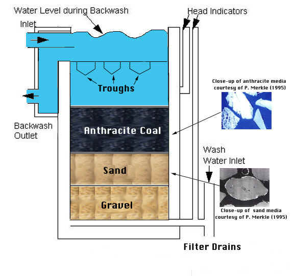 Schematic of filter bed. Christie Shinault and Dottie Schmitt Filter media selection (both size and type) may be the most important decision in a rapid sand filter design. Its selection is specific to each treatment plant and depends on the type of influent being filtered, media available and expected quality of effluent. Filter InletThe inlet consists of a method of maintaining a set water level during filtration and removing waste during the backwash cycle. Weirs are the most common method used to maintain the water level.
Wash trough photos courtesy of Dr. Daniel L. Gallagher A series of wash troughs are used to collect and remove backwash water. Wash troughs are usually located 3.5 - 4 feet above the bed, 6 - 10 feet apart. Correct spacing and height of troughs ensures the dirty wash water is efficiently skimmed off, without washing out any of the filter media. Filter OutletThe outlet consists of a method to collect and remove filter water, distribute backwash water and control flow rate through the filter. Collection and distribution is accomplished with an under drain, commonly called a filter floor as it may also support the filter bed. There are three main designs commonly used:
If the filter design is decreasing flow, then no flow control is used. As the filter bed fills with particulate matter the flow is reduced as more energy is expended in head losses. When head loss reaches a set maximum, cleaning by backwashing is required. Steady flow type filters are the most common. In |
 12 - 18 inches of
anthracite coal with a specific gravity of 1.5 and grain size of 0.7 - 2 mm..
The anthracite has a larger, more angular particle size to trap particulate
matter before it gets to the sand layer and clogs it. Anthracite's lower
specific gravity allows it to remain on top of the sand layer after backwashing.
The anthracite layer also allows a lower backwash velocity to give the same bed
expansion than if sand alone were used.
12 - 18 inches of
anthracite coal with a specific gravity of 1.5 and grain size of 0.7 - 2 mm..
The anthracite has a larger, more angular particle size to trap particulate
matter before it gets to the sand layer and clogs it. Anthracite's lower
specific gravity allows it to remain on top of the sand layer after backwashing.
The anthracite layer also allows a lower backwash velocity to give the same bed
expansion than if sand alone were used.